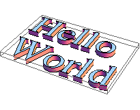
When importing PDF files Mathematica 6-7 converts glyphs to polygons. We can utilize this fact to get outlines of these glyphs which can be further processed as desired. Here I will show how to make arbitrary font/glyph combinations into 3D objects.
NOTE: this code depends on a specific behavior of Mathematica's PDF import feature. This code may break if future versions of Mathematica change the way glyphs from PDF files are imported.
As I mentioned previously, Mathematica's PDF import simulates polygons/paths with holes by connecting the different segments/contours with 0-width lines. There is a break in a contour where these 0-width lines occur. This first function finds the points which comprise the 0-width lines.
FindContourBreaks[pts_List] := Module[
{i, lines, breaks = {}},
lines = {pts[[#[[1]]]], pts[[#[[2]]]]}& /@
Partition[RotateLeft[Flatten[{#, #}& /@
Range[Length[pts]], 1]], 2];
For[i = 1, i <= Length[lines], i++,
If[MemberQ[lines, {lines[[i, 2]], lines[[i, 1]]}],
AppendTo[breaks, i]
];
];
breaks
];
{i, lines, breaks = {}},
lines = {pts[[#[[1]]]], pts[[#[[2]]]]}& /@
Partition[RotateLeft[Flatten[{#, #}& /@
Range[Length[pts]], 1]], 2];
For[i = 1, i <= Length[lines], i++,
If[MemberQ[lines, {lines[[i, 2]], lines[[i, 1]]}],
AppendTo[breaks, i]
];
];
breaks
];
This function returns a list of the individual polygon contours.
FindContours[pts_List] := Module[
{breaks, ranges},
breaks = FindContourBreaks[pts];
ranges = Partition[RotateLeft[Join[{1, 1},
Flatten[{#, # + 1}& /@ breaks]]], 2];
ranges = Drop[ranges, - 1];
DeleteCases[Take[pts, #]& /@ ranges, x_ /; Length[x] < 3]
];
{breaks, ranges},
breaks = FindContourBreaks[pts];
ranges = Partition[RotateLeft[Join[{1, 1},
Flatten[{#, # + 1}& /@ breaks]]], 2];
ranges = Drop[ranges, - 1];
DeleteCases[Take[pts, #]& /@ ranges, x_ /; Length[x] < 3]
];
Now that we have a list of the contours we can process them further. Here I will convert them from a 2D polygon to a object. The top of the object will be the 2D polygon living in 3D space. The bottom will be the reverse of the top (to get the lighting correct) offset a certain depth below the top. Finally, I will add a sequence of rectangles orthogonal to the top and bottom to form the sides of the object to close it in.
ThreeDContour[pts_List, depth_] := Module[
{topPts, botPts, sideRects, sidePts, sideNormals},
topPts = {#[[1]], #[[2]], 0}& /@ pts;
botPts = (# + {0., 0., - depth})& /@ topPts;
sideRects = Partition[RotateLeft[Flatten[{#, #}& /@
Range[Length[topPts]], 1]], 2];
sidePts = {
topPts[[#[[1]]]], botPts[[#[[1]]]],
botPts[[#[[2]]]], topPts[[#[[2]]]]
}& /@ sideRects;
Polygon /@ sidePts
];
ThreeDContours[pts_List, depth_] := Module[
{contours},
contours = FindContours[pts];
ThreeDContour[#, depth]& /@ contours
];
{contours},
contours = FindContours[pts];
ThreeDContour[#, depth]& /@ contours
];
ThreeDPolygon[Polygon[pts_List], depth_] := Module[
{topPts, botPts, sidePolys},
topPts = {#[[1]], #[[2]], 0}& /@ pts;
botPts = Reverse[(# + {0., 0., - depth})& /@ topPts];
sidePolys = ThreeDContours[pts, depth];
{Polygon[topPts], Polygon[botPts], EdgeForm[], sidePolys}
];
{topPts, botPts, sidePolys},
topPts = {#[[1]], #[[2]], 0}& /@ pts;
botPts = Reverse[(# + {0., 0., - depth})& /@ topPts];
sidePolys = ThreeDContours[pts, depth];
{Polygon[topPts], Polygon[botPts], EdgeForm[], sidePolys}
];
This function converts a 2D graphics scene to a 3D graphics scene where all the 2D polygons are made into 3D objects with the given depth.
ThreeDGraphics[gfx_Graphics, depth_] :=
gfx /. Polygon[pts_List] :> ThreeDPolygon[Polygon[pts], depth] /.
(PlotRange -> _) :> PlotRange -> All /.
Graphics[gfx2D___] :> Graphics3D[gfx2D];
gfx /. Polygon[pts_List] :> ThreeDPolygon[Polygon[pts], depth] /.
(PlotRange -> _) :> PlotRange -> All /.
Graphics[gfx2D___] :> Graphics3D[gfx2D];
These final two functions will take an arbitrary piece of text in an arbitrary font, export it to PDF, import the PDF back into Mathematica (to convert the glyphs to outlines), and make them 3D.
ThreeDText[str_String, family_String:"Times", depth_:10] :=
ThreeDGraphics[TwoDText[str, family], depth];
ThreeDGraphics[TwoDText[str, family], depth];
TwoDText[str_String, family_String:"Times"] :=
First[ImportString[ExportString[Cell[str, FontSize -> 100,
FontFamily -> family], "PDF"], "PDF"]];
First[ImportString[ExportString[Cell[str, FontSize -> 100,
FontFamily -> family], "PDF"], "PDF"]];
Finally, we can see the results.
ThreeDText["Hello\nWorld"]
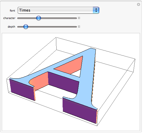
We could also build an interface that allows us to choose which glyph in which font we want.
Manipulate[
Show[
ThreeDText[FromCharacterCode[character], font, depth],
ImageSize->{Automatic, 300}
],
{{font, "Times"},
Map[First, FE`Evaluate[FEPrivate`GetPopupList["MenuListFonts"]]]},
{{character, 65}, 33, 127, 1},
{{depth, 10}, 0, 100}
]
Show[
ThreeDText[FromCharacterCode[character], font, depth],
ImageSize->{Automatic, 300}
],
{{font, "Times"},
Map[First, FE`Evaluate[FEPrivate`GetPopupList["MenuListFonts"]]]},
{{character, 65}, 33, 127, 1},
{{depth, 10}, 0, 100}
]


3 comments:
I had been trying to figure out how to do something like this. This code is wonderful; thank you for posting it.
Wonderfull.
The only limitation is of the Mma itself,
(at least in Linux systems) which cannot properly deal with other character encodings when exporting to PDF.
However using open office export to PDF and Mma Import[] allows easily reuse this very clear code. Thanks a lot.
Hi,
I tried your code “Font outlines and 3D text” and got this error:
FilledCurve is not a Graphics3D primitive or directive.
Can you help me fix this?
Post a Comment